
Motivation
In the first assignment, you wrote code to read and manipulate a 3D model from a file in obj format. For this assignment, you will take the first step in rendering a scene using a ray casting algorithm. More precisely, you write a program that reads in a camera model and one or more objects (defined in a driver file) and your code will produce a pseudo-colored depth image in which color indicates relative distance from the image plane. This distance is a critical value computed and returned by the basic ray to surface intersection code. While the resulting scene is not a realistic rendering, the code for manipulating camera geometry, casting rays, determining closest points of intersection, etc. will all be readily extended in the assignment 3 to handle light sources and render scenes.
Task
Your program will take in two command line arguments. The first argument is a driver file containing the camera description and a list of models along with their model-to-world transformations. The second argument is the name of the image your program will write back to the disk in the same folder where your executable is located. A C++ example is:
$./raytracer driver00.txt driver00.ppm
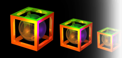
Your program will implement the camera model by throwing a ray from each camera pixel and determining the closest surface, if any, which lies in the path of the ray. Presuming the ray intersects a surface, then the pixel should be set to a color value indicating how far that surface is from the camera, i.e. the pixel. The precise algorithm for determining color will be supplied below so that all assignments generate consistent coloring. Should a ray fail to intersect any polygon then it is given a default background color; for this assignment set this default to (239, 239, 239). Your program will then write out the resulting image as an ASCII PPM color image (P3 format, details provided below) to the filename in the second argument passed to your executable.
Data Formats
Here are the contents of a sample driver file:
				# you may include comments here
 eye 4 4 4
 look 0 0 0

				up 0 0 1
 d 2
 bounds -1 -1 1 1
 res 256 256

				sphere -1 -1 -1 1
 model 0.0 1.0 0.0 45 1.0 1.0 0.0 1.0
				cube.obj
The contents of the camera specification should be familiar to you now. The first line represents a comment. The next three lines supply the location of the focal point (the Eye), the look at point, and the up vector. Then comes the focal length, i.e. the distance from the focal point to the image plane (near clipping plane). Pay particular attention to the next two arguments. The 'bounds' values indicate the minimum and maximum extend of the bounded image rectangle on the infinite image plane in the camera horizontal and vertical directions respectively. Then the resolution values separately indicate the pixel sampling resolution across the horizontal and vertical dimensions of the bounded rectangle. One feature of this specification format is that you can generate intermediate cameras with low resolution, say 8 by 8 or even 4 by 4, when developing and debugging code. This speeds development considerably. Do note that the dimensions of your output image must match the resolution specification exactly; no off by one errors allowed.
Finally, you could have zero or more spheres and/or zero or more models. A sphere is represented by keyword sphere followed by three numbers cx, cy, and cz which represent the center of the sphere in world coordinates, followed by the fourth number representing the radius of that sphere. Note that you do not have to do model-to-world transformation for spheres since they will already be represented in the world coordinate system. Next, the model will follow same formatting as it was in the first assignment (model wx wy wz theta scale tx ty tz model.obj). You need to perform model-to-world transformations for all the models given in the driver file.
For this assignment you may assume that the row structure, including the single word headers on each line, do not change in a driver file. You need to ignore any comment lines.
Images should be written as legal ASCII PPM files. Although some variations are permissible, I recommend the following. The first line contains the characters P3 and nothing else. The next line contains the image width, the image height, and the number 255 (the maximum possible pixel value), all integers. Pixel values begin on the next line, and contain 3 values per pixel (a red value, a green value, and a blue value, in that order). Since the total number of pixels in an image is width times height, the number of values in the file (after the two header lines) must be 3 times width times height. To make images “readable” by humans (when they are small), you will want to put a newline at the end of each row. The image generated from this driver file might therefore begin with:
				P3
 256 256 255
 239 239 239 239 239 ...
The models to be used in this assignment are specified in WaveFront OBJ. In this format the faces will be limited to 3 vertices. In other words, you need only consider the intersection of a ray with a triangle as opposed to an arbitrary polygon.
Relative Depth
You encoding of relative depth must follow exactly the following
specification. First, when your algorithm completes ray casting for
every pixel, record the
tmin
and
tmax
values. To be clear, these are the minimum and maximum distances from
pixels to first polygons as determined by the t value returned when a
ray intersects a polygon. Then, for every pixel intersecting a
polygon, use the resulting
t
value to determine color as follows:
				ratio = 2 * (t - tmin) / (tmax - tmin)
 r = max(0, 255 * (1 -
				ratio))
 b = max(0, 255 * (ratio - 1))
 g = 255 - b - r
Credit where credit is due, this simple code for generating a thermal color map originated from a post by John1024.
Notice that to create the color coding your code must have determined all t values. A brute force approach is a two pass system that essentially ray casts the scene twice. A better approach would be to record the t-value to the nearest surface for every pixel in an intermediate data structure, a 2D array, and then use that structure to find the min and max t-values and finally to generate the color output image.
Examples
You are being provided a few models and six driver files along with the output images generated by the reference system for this assignment. While your output may not match perfectly, it should come very close. All the example files, unix encoded, are included in the following zip file:
You may find the simface.obj example from driver00.txt helpful in debugging your code since it has only two faces and a low resolution rendering.
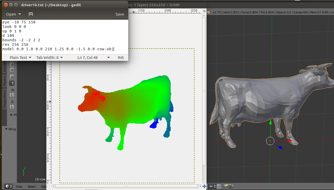
Here is a montage showing an example with the driver file, output image, and a view of the cow.obj model using the Blender software. Note that you will be applying transformations to the obj models as they are defined in driver file. In this example the cow object is transformed and therefore you see the change in orientation, scale, and position of cow as compared to the original cow.obj
Submission
Submit a tar file via the CANVAS assignment page that includes:
- Your source files
- A makefile if appropriate
- README.txt file that explicitly contain (1) A command to compile
your program and (2) A command to execute it.
If you are using C++, your executable should be named 'raytracer'. If your are using java, the main executable class should be named 'Raytracer'. Notice the change in case for the first letter between C++ and Java. It is must for this assignment to take exactly two arguments as described above.
Reminder
There is no “late period”. Key is to start earlier and finish earlier. The program is due when it is due. All work you submit must be your own. You may not copy code from colleagues or the web or anywhere else. Cheating will not be tolerated, and will be handled in accordance with university and department policy.
Addendum (Last update 10/7/17)
Please note that the output of driver02.txt (driver02.ppm) has been updated in the examples.zip, and it is different from what you were provided earlier.
Following text file gives the tmax and tmin values for all the driver files given to you tmax_tmin.txt
Before submitting your tarball, please check Piazza post for safe grading.
Addendum (Last update 10/20/17)
Here are the remaining unknown test cases with their tmax and tmin values: testcases.zip