
Motivation
In the past assignment you wrote code to read a 3D model and a 3D camera specification and then carry out model transformations and ray casting, but stopping just short of rendering a scene with material properties and lighting. In this assignment you now will have lighting, material properties for spheres and models. You will be asked to demonstrate that your ray casting system is capable of rendering the scenes described in the driver files given to you.
In this assignment you are explicitly not being asked to perform recursive ray tracing nor are you being asked to handle semi-transparent objects. In other words, no light refracting through spheres. You may anticipate these as additions to next assignments.
Data Formats
The driver file, as you may have figured out, is specific to this class and this semester of CS 410. Additions have been made to the driver file for this assignment to support scene lighting. If necessary, do review the driver specification from Assignment 2. Here is an example of a driver file for this assignment.
				# you may include comments here
 eye 4 4 4
 look 0 0 0

				up 0 0 1
 d 2
 bounds -1 -1 1 1
 res 256 256

				ambient 0.1 0.1 0.1
 light 0 4 4 1 0.50 0.25 0.25
 light
				4 0 4 1 0.25 0.50 0.25
 sphere -1 -1 -1 1 0.2 0.2 0.2 0.5 0.5
				0.5 0.5 0.5 0.5 0.9 0.9 0.9
 model 0.0 1.0 0.0 45 1.0 1.0 0.0
				1.0 cube.obj
The initial seven lines of the file are identical to before. New is the facility to specify multiple light sources.
After resolution is specified, note the next line specifies the ambient illumination in the scene. This is a low level 'white' light with values of 0.1 for red, green, and blue bands on a scale of zero to one. After specifying the amount of ambient light in the scene, zero or more light sources may be specified. The first four values given are the x, y, z and w coordinates of the light source in world coordinates. The fourth value w is generally one, but a zero indicates a light source at infinity in the direction specified by x, y, and z. The last three values indicate the red, green, and blue levels of the light source on a zero to one scale.
Following the light sources come zero or more spheres. The first three values are the x, y and z coordinates of the sphere in world coordinates. The fourth value is the radius of the sphere. All the next values are the simplified material properties indicating the 'color' of the sphere in terms of red, green and blue. First triplet after the radius represents (Ka_red, Ka_green, Ka_blue) ambient coefficients. Next triplet represents diffuse (Kd_red, Kd_green, Kd_blue) coefficients. Next we have (Ks_red, Ks_green, Ks_blue) specular coefficients. Finally, we have (Kr_red, Kr_green, Kr_blue) attenuation coefficients.
Finally, zero or more polygonal models may be specified for inclusion in the scene. Note that the format of polygonal model inclusion is exactly the same as it was for the previous assignment.
Here is a very important detail not to overlook. The *.obj file for a model probably in turn specifies a material file that your program must load to understand the material properties associated with the faces in the model. A material file has a standard format with .mtl extension. From this file you will be using Ka, Kd, Ks coefficients. More will be said about material files in lecture and examples will be shown.
Task
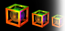
In this assignment you will construct three scenes described in the three driver files given to you.
In all cases the camera view, lighting, and model transformations and placement should result in a well rendered final image. The image should be written in PPM format just as you did for the previous assignment (see Assignment 2 for details on PPM format). Here are the example ppm outputs for the driver files. Note that your ppms may not exactly match with these and they may vary slighly depending on the method used for face normal calculation.Your program will take in two command line arguments. The first argument is a driver file containing the camera description and a list of models along with their model-to-world transformations. The second argument is the name of the image your program will write back to the disk in the same folder where your executable is located. A C++ example is:
$./raytracer driver00.txt driver00.ppm
Submission
Submit a tar file via the CANVAS assignment page that includes:
- Your source files
- A makefile if appropriate
- README.txt file that explicitly contains (1) A command to compile
your program and (2) A command to execute it.
Before submitting your tarball, please check Piazza post for safe grading.
If you are using C++, your executable should be named 'raytracer'. If your are using java, the main executable class should be named 'Raytracer'. Notice the change in case for the first letter between C++ and Java. It is must for this assignment to take exactly two arguments as described above.
Reminder
There is no “late period”. Key is to start earlier and finish earlier. The program is due when it is due. All work you submit must be your own. You may not copy code from colleagues or the web or anywhere else. Cheating will not be tolerated, and will be handled in accordance with university and department policy.
Addendum (Last update 10/23/17)
The driver02.txt and its corresponding driver02.ppm has been updated in the .zip folders above. (10/23/17 Guru)