Start from the following skeleton file: eLC-3.circ, but read this entire document before panicking.
This assignment will be auto-graded. Don't change the name of the sub-circuits and don't create or remove sub-circuits. Pay attention to the notes inside the input, output, and reserved sections.
You will be designing and implementing the controller for a subset of the LC-3. We'll call this processor the eLC-3 (Even Littler Computer 3). The eLC-3 only supports the following instructions:
There are two deliverables:
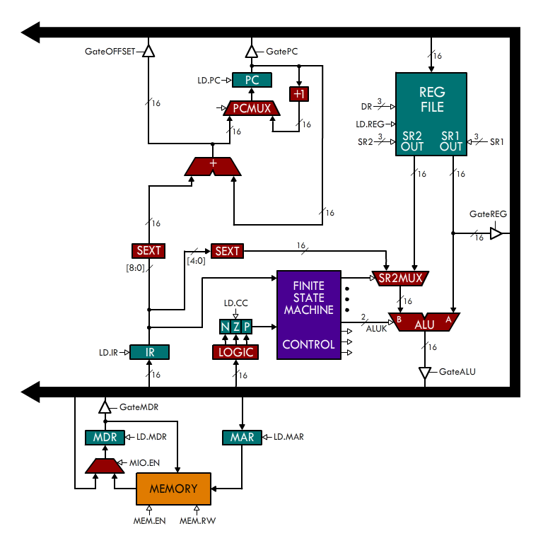
Here's the datapath for the eLC-3:
In the skeleton file, you'll find two circuits: eLC-3 and Controller. The eLC-3 circuit is just the Logisim implementation of the datapath shown above. You don't have to (and must not) do anything to this circuit, so don't be intimidated by it. Initially, you will see a lot of blue and red wires. That's because you must complete the Controller circuit. Notice the FSM chip next to the clock? This is an instance of the Controller circuit. This circuit is the state machine that controls the movement of information in the datapath. This is what you will be designing. Essentially, we're giving you the body (the datapath) and you must give it a soul (the controller).
In the previous assignment, you dealt with state machines with one bit for the input and one bit for the output. The state machine in this assignment is richer. The inputs are the IR and the CC. The outputs are the control signals. You must design your state machine to activate the right control signals at the right time. We're not enforcing a specific number of states or a specific state encoding for your state machine. However, we do require a specific number of cycles for each instruction:
The state machine is a Mealy machine but the outputs are not latched (they don't go through a flip flop): the output is simply a function (implemented using combinational logic) of the current state and the input. Our solution uses 7 states, so it's not a gigantic state machine. Don't make this assignment more complicated than it really is.
Don't introduce a clock in your state machine. Instead, use the CLOCK input as the clock. This input is connected to the clock in the datapath. Also, use only D Flip Flops and elements from the Wiring and Gates libraries.
Preliminary testing will check that your submission behaves correctly with a NOT instruction. You must pass preliminary testing by the first due date shown above. The complete assignment is due on the second due date.
As intimidating as it looks, the layout of the Logisim datapath is very close to the nice picture above. Here are some details that you need to know about the datapath:
We will test your submission by loading a program in memory, running it, and inspecting the result. You can do the same. Suppose you wanted to test the following program, test.asm:
.ORIG x0000
NOT R2, R1
.END
First, notice that I'm using x0000 instead of the usual x3000 for the .ORIG. This is because it's not easy to load the program in a location other than x0000 in the eLC-3.
Let's assemble this into a format that Logisim can understand. Use the following command (you may need to adapt it to your environment):
~cs270/lc3tools/lc3as -hex test.asm && sed -i "1s/.*/v2.0 raw/" test.hex
This generates the following file, test.hex:
v2.0 raw
947f
Notice that 947f is just the hexadecimal translation of NOT R2, R1. Now, go to the eLC-3 circuit in Logisim. Right click on the memory element and select Load Image. Select the test.hex file. This populates memory with your program.
Now click on the CC register and change its value to 2. For this program, this is not needed. However, if the first thing in your program is an unconditional BR instruction, it is necessary for the CC to be set to something that is not 0 so that it actually branches.
You may also want to change the value of R1 so that you can check that R2 eventually becomes ~R1.
When you're ready to run your program, click on the clock twice. This makes the clock go high and then low. This is one cycle. Check if the expected register transfers occurred. Keep repeating until the program is completed and check that the registers end up with the right values. You can always check the value present on a wire by clicking on it with the hand tool.
Now that you read the entire document, you may panic at will. :-)
When finished, submit your eLC-3.circ file to the H3 box in the Checkin tab.