*** READ THIS SECTION CAREFULLY ***
Start from the following skeleton file: H2.circ
When finished, submit your H2.circ file to the H2 box in the Checkin tab. Preliminary testing will perform some sanity tests, but it will not check that you got the right answers. There is also a Canvas component. Refer to each problem for details.
This assignment will be auto-graded. Don't change the name of the sub-circuits and don't create or remove sub-circuits. Pay attention to the notes inside the input, output, and reserved sections. If you don't pass preliminary testing, the auto-grader will be unable to grade your work and you won't get credit.
Design and draw the state diagram of a Mealy machine (i.e., outputs are transition-assigned) to control a mean-spirited vending machine, MVM. It charges 30 cents for a small toy and does not render change (all extra money is gladly accepted), but at least it delivers the toy (output signal T becomes 1). Moreover, MVM only accepts dimes and quarters (as input signals named D and Q). Since the human input is much slower than the clock of the machine, there are many clock cycles when both D and Q are zero, but the condition D = Q = 1 is guaranteed to never occur (only one coin may be inserted).
Here are some important specifications:
Do not use symbols like 01, 11, etc. If you do so, you will lose points.
To draw the diagram, you must use yEd. We suggest you try yEd Live in the browser rather than installing the software to avoid java incompatibility issues.
If you want to run this program in one of the CS machines, download the Java zip file from that page (you may need to click on Show all versions). In a terminal, go to the folder where you downloaded the file and run the following commands:
unzip yEd-3.17.zip
cd yed-3.17
java -jar yed.jar
To draw an edge from a state to the same state in yEd, use the Polyline with Target Arrow edge. Click and hold on a node, drag the mouse out of the node in any direction, release the mouse and then click on the node again. Here is a short demo on doing this and naming edges: click here.
When you're done, export your graph as a PDF (File > Export...) and submit it to the H2P1 Canvas assignment.
In this problem, you will design a circuit that implements the combinational part of the following state machine:
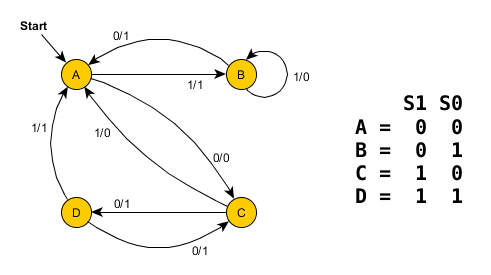
You must use the state encoding shown on the right. Note that S1 is the most significant bit of the state and S0 is the least significant bit. The input to the state machine will be labeled In. The output of the state machine will be labeled Out.
In this problem, you will design a circuit that implements the following state machine:
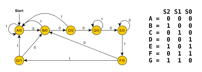
You must use the state encoding shown on the right. Note that S2 is the most significant bit of the state and S0 is the least significant bit. Also, notice that the state encoding is unusual: it's not in increasing binary order. Be careful about this when building your state table. The input to the state machine will be labeled In. The output of the state machine will be labeled Out. This is a Moore state machine since the output only depends on the current state.
Advanced question (for fun): can you write the regular expression that this state machine recognizes?