Start from the following files that provide a partial implementation of eLC-3 that you will complete. Read this entire document before panicking.
You will complete the design and implementation of the eLC-3. The eLC-3 only supports the following instructions:
There is one submission for this assignment:
This assignment will be auto-graded. Don't change anything on the eLC-3 datapath circuits. Don't change the input or output sections on the eLC-3 controller. You should only change the logic circuits on the eLC-3 controller to support instruction fetch and decode, state transitions, and control signals generated. Pay attention to the notes inside the input, output, and reserved sections.
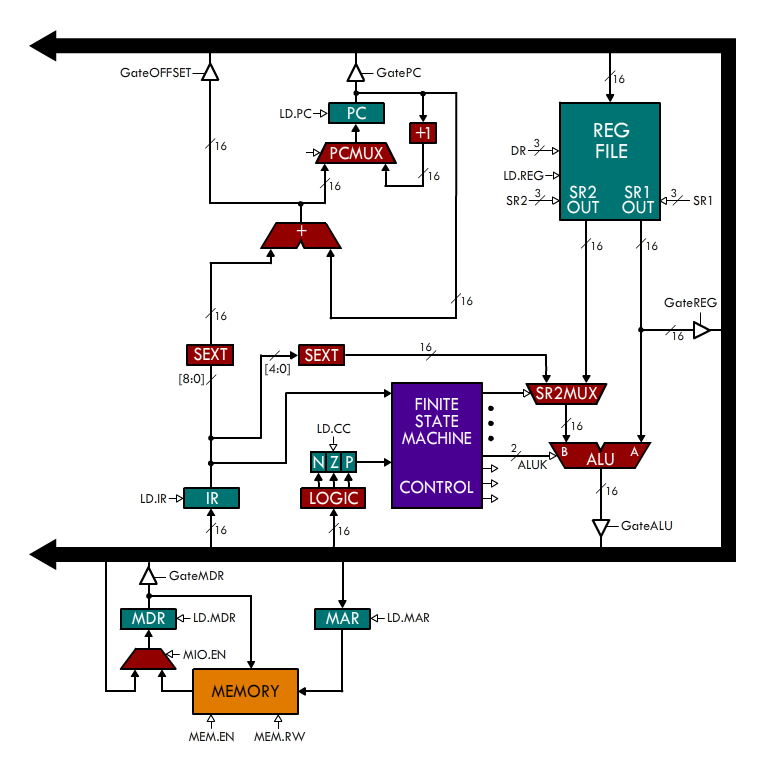
Here's the datapath for the eLC-3. The ADDR1MUX, ADDR2MUX, MARMUX, and GateMARMUX logic have been replaced by GateOFFSET and GateREG.
In the skeleton file, you'll find two circuits: eLC-3 and Controller. The eLC-3 circuit is just the Logisim implementation of the datapath shown above. You don't have to (and must not) do anything to this circuit, so don't be intimidated by it. Initially, you will see a lot of blue and red wires. That's because you must complete the Controller circuit. Notice the FSM chip next to the clock? This is an instance of the Controller circuit. This circuit is the state machine that controls the movement of information in the datapath. You will be completing the implementation of the FSM circuit.
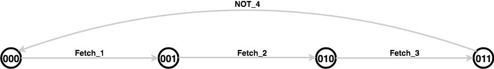
In the previous assignment, you dealt with state machines with one bit for the input and one bit for the output. The state machine in this assignment is richer. The inputs are the IR and the CC. The outputs are the control signals. You must complete the state machine:
The state machine is a Mealy machine but the outputs are not latched (they don't go through a flip flop): the output is simply a function (implemented using combinational logic) of the current state and the input. The solution only requires 7 states, so it's not a gigantic state machine. The 3 state bits provided in the controller are sufficient for your implementation. You may wish to complete the truth table before implementing the circuit. Refer to the LC-3 visualization or state diagram for details about the LC-3.
Do not introduce a clock in your state machine. Instead, use the CLOCK input as the clock. This input is connected to the clock in the datapath. Also, use only elements from the Wiring and Gates libraries.
As intimidating as it looks, the layout of the Logisim datapath is very close to the picture above. Here are some details that you need to know about the datapath:
We will test your submission by loading a program in memory, running it, and inspecting the result. You can do the same. Suppose you wanted to test the following program, test.asm, after you have completed the instruction fetch and NOT instruction:
.ORIG x0000
NOT R2, R1
.END
First, notice that I'm using x0000 instead of the usual x3000 for the .ORIG. This is because it's not easy to load the program in a location other than x0000 in the eLC-3.
Let's assemble this into a format that Logisim can understand. Use the following command (you may need to adapt it to your environment):
~cs270/lc3tools/lc3as -hex test.asm && sed -i "1s/.*/v2.0 raw/" test.hex
This generates the following file, test.hex:
v2.0 raw
947f
Notice that 947f is just the hexadecimal translation of NOT R2, R1. Now, go to the eLC-3 circuit in Logisim. Right click on the memory element and select Load Image. Select the test.hex file. This populates memory with your program.
Now click on the CC register and change its value to 2. For this program, this is not needed. However, if the first thing in your program is an unconditional BR instruction, it is necessary for the CC to be set to something that is not 0 so that it actually branches.
You may also want to change the value of R1 so that you can check that R2 eventually becomes ~R1.
When you're ready to run your program, click on the clock twice. This makes the clock go high and then low. This is one cycle. Check if the expected register transfers occurred. Keep repeating until the program is completed and check that the registers end up with the right values. You can always check the value present on a wire by clicking on it with the hand tool.
Now that you read the entire document, you may panic at will. :-)
When finished, submit your eLC-3.circ file to the R14 box in the Checkin tab.