
Motivation
In the past assignment you wrote code for a ray casting system capable of rendering the scenes described in the driver files. In this assignment you will be adding to your existing ray tracing software a capability to perform reflection i.e., recursive ray tracing. This will include the ability to control the depth of recursion though your driver files. Moreover, your code should now be able to handle shadows and multiple materials described in the .mtl file that is associated with the model (.obj) file.
Data Formats
The driver file used here is identical in format to that used in the previous assignment with one exception. There is a new field specifying the recursion depth. Note this line follows the line specification of resolution as shown in this example:
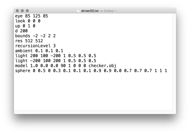
As in the SageMath notebooks, a recursion level of zero means there will be no recursive ray tracing performed and your code will revert to ray-casting as in the previous assignment.
Here is a very important detail not to overlook. The .mtl file associated with the *.obj file will contain more than one materials. This is a change from the previous assignment. Also, every face from the .obj file will have a material (one of the several materials described in the .mtl file) associated with it. When rendering a face your program will read in the appropriate material linked with that face. You should use Ns, Ka, Kd, and Ks fields from the .mtl file. For spheres use phong constant = 16.
Task
Unlike the previous assignments, in this assignment you most design and the render your own scenes. While you are being given some test cases, an important part of the assignment is for you to demopnstrate a hands-on understanding of how to create a scene. In turn, a big part of what makes your new scenes interesting will be in the interaction of objects through reflections and shadoes. To accomplish this assignment there are three principle tasks:
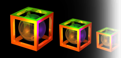
- Implement a recursive ray tracer. For details of how this should be done, please use the Sage Notebook illustrations presented in lecture. You are also being askedd to design a visually interesting scene where evidence of recursion is clearly visible. At a minimum, somewhere in the scene a viewer should see clearly that some object A is reflected in a second object B that is in turn reflected in an object C.
- Write code that renders scenes with shadows. This is done by testing for each point light source whether it has a clear view of the surface point being illuminated. If not, then that light source does not contribute to the illumination of the surface point.
- The ability to read multiple materials associated with a single .obj file and in so doing vary how individual faces within and object appear.
In this assignment your code will be responsible for correctly rendering four scenes, two of which are described in the driver files given to you in the .zip below and the other two will of your choice while adhering to the guidelines described below.
- Scene 0:
- The scene described in driver00.txt
- Scene 1:
- The scene described in driver01.txt
- Scene 2 (name it driver02.txt):
- Construct a scene using two Polygonal models consisting of at least 100 triangles. Light the scene with at least two point light sources. You may use a single material for these models. Use a recursion level of 5.
- Scene 3 (name it driver03.txt):
- Construct a scene involving at least four spheres. Light this scene using at least two point light sources. Use a recursion level of 5. Demonstrate that you your code properly handles occlusion between the spheres in the scene.
Your program will take two command line arguments. The first argument is a driver file. The second argument is the name of the image your program will write back to the disk in the same folder where your executable is located. A C++ example is:
$./raytracer driver00.txt driver00.ppm
Submission
Submit a tar file via the CANVAS assignment page that includes:
-
Driver files (driver02.txt and driver03.txt) and model files
necessary to demonstrate scene 2.
-
PPM files generated for driver02.txt and driver03.txt
- Your source files
- A makefile if appropriate
- README.txt file that explicitly contains (1) A command to compile
your program and (2) A command to execute it.
Before submitting your tarball, please check Piazza post for safe grading.
If you are using C++, your executable should be named 'raytracer'. If your are using java, the main executable class should be named 'Raytracer'. Notice the change in case for the first letter between C++ and Java. It is must for this assignment to take exactly two arguments as described above.
Reminder
There is no “late period”. It is essential to start earlier and finish earlier. The program is due when it is due. All work you submit must be your own. You may not copy code from colleagues or the web or anywhere else. Cheating will not be tolerated, and will be handled in accordance with university and department policy.
Addendum (Last update: Guru 11/24/17)
driver00.txt and driver00.ppm are updated
Submission instructions are updated