Introduction to Computer Graphics
Fall 2018
CS 410 P2 - Diffuse Illumination

Motivation
In the first assignment, you wrote a code to read and manipulate a 3D model from a file in obj format. For this assignment, you will take the first step in rendering a scene with multiple objects and a light sources. More precisely, you will write a program that reads 3D camera specifications and one or more 3D objects defined in a driver file. To render a colorful scene, you will also read light source specifications and material properties of the objects. You will be asked to demonstrate that your ray casting system is capable of rendering the scenes described in the driver files given to you.
Your illumination model in this assignment will only include ambient and diffuse components. Specular reflection will be added in the next assignment. Also, you are explicitly not being asked to perform recursive ray tracing nor are you being asked to handle semi-transparent objects. In other words, no light refracting through spheres. You may anticipate these as additions later in the semester.
Your program will take in two command line arguments. The first argument is a driver file containing the camera description and a list of models along with their model-to-world transformations. The second argument is the name of the image your program will write back to the disk in the same folder where your executable is located. A C++ example is:
$./raytracer driver00.txt driver00.ppm
The models to be used in this assignment are specified in WaveFront OBJ. In this format the faces will be limited to 3 vertices. In other words, you need only consider the intersection of a ray with a triangle as opposed to an arbitrary polygon.
Your program will implement the camera model by throwing a ray from each camera pixel in near clipping plane and determining the closest surface, if any, which lies in the path of the ray. Presuming the ray intersects a surface, then the pixel should be set to a color value determined by the material properties and lighting specifications in the scene. Should a ray fail to intersect any polygon then it is given a default background color; for this assignment set this default to (0, 0, 0). Your program will then write out the resulting image as an ASCII PPM color image (P3 format, details provided below) to the filename in the second argument passed to your executable.
Data Formats
The driver file, as you may have figured out, is specific to this class and this semester of CS 410. Additions have been made to the driver file for this assignment to support camera specifications and scene lighting. If necessary, do review the driver specification from Assignment 1. Here is an example of a driver file for this assignment.
				# you may include comments here
 eye 4 4 4
 look 0 0 0

				up 0 0 1
 d 2
 bounds -1 -1 1 1
 res 256 256

				ambient 0.1 0.1 0.1
 light 0 4 4 1 0.50 0.25 0.25
 light
				4 0 4 1 0.25 0.50 0.25
 model 0.0 1.0 0.0 45 1.0 1.0 0.0 1.0
				cube.obj
The contents of the camera specification should be familiar to you now. The first line represents a comment. The next three lines supply the location of the focal point (the Eye), the look at point, and the up vector. Then comes the focal length, i.e. the distance from the focal point to the image plane (near clipping plane). Pay particular attention to the next two arguments. The 'bounds' values indicate the minimum and maximum extend of the bounded image rectangle on the infinite image plane in the camera horizontal and vertical directions respectively. Then the resolution values separately indicate the pixel sampling resolution across the horizontal and vertical dimensions of the bounded rectangle. One feature of this specification format is that you can generate intermediate cameras with low resolution, say 8 by 8 or even 4 by 4, when developing and debugging code. This speeds development considerably. Do note that the dimensions of your output image must match the resolution specification exactly; no off by one errors allowed.
After resolution is specified, note the next line specifies the ambient illumination in the scene. This is a low level 'white' light with values of 0.1 for red, green, and blue bands on a scale of zero to one. After specifying the amount of ambient light in the scene, zero or more light sources may be specified. The first four values given are the x, y, z, and w coordinates of the light source in world coordinates. The fourth value w is generally one, but a zero indicates a light source at infinity in the direction specified by x, y, and z. The last three values indicate the red, green, and blue levels of the light source on a zero to one scale.
Finally, zero or more polygonal models will be specified for inclusion in the scene. Note that the format of polygonal model inclusion is exactly the same as it was for the previous assignment.
Here is a very important detail not to overlook. The *.obj file for a model specifies a material file that your program must load to understand the material properties associated with the faces in the model. A material file has a standard format with .mtl extension. From this file you will ONLY be using Ka and Kd coefficients. For this assignment you will not read the ks coefficient that determines the specular highlights on the object. More will be said about material files in lecture and examples will be shown.
PPM Image Format:
Images should be written as legal ASCII PPM files. Although some variations are permissible, I recommend the following. The first line contains the characters P3 and nothing else. The next line contains the image width, the image height, and the number 255 (the maximum possible pixel value), all integers. Pixel values begin on the next line, and contain 3 values per pixel (a red value, a green value, and a blue value, in that order). Since the total number of pixels in an image is width times height, the number of values in the file (after the two header lines) must be 3 times width times height. To make images “readable” by humans (when they are small), you will want to put a newline at the end of each row. The image generated from this driver file might therefore begin with:
				P3
 256 256 255
 239 239 239 239 239 ...
Task
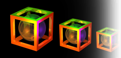
In this assignment you will construct three scenes: two scenes described in the two driver files given to you and one more scene of your choice by creating your own driver file with any polygonal object of your choice.
In all cases the camera view, lighting, and model transformations and placement should result in a well rendered final image. The image should be written in PPM format as described above. Here are the example ppm outputs for first two driver files. Note that your ppms may not exactly match with these but they should come very close.Submission
Submit a tar file via the CANVAS assignment page that includes:
- Your source files
- Your driver files
- Libraries if you use any
- A makefile if appropriate
- README.txt file that explicitly contains (1) A command to compile your program and (2) A command to execute it.
If you are using C++, your executable should be named 'raytracer'. If your are using java, the main executable class should be named 'Raytracer'. Notice the change in case for the first letter between C++ and Java. It is must for this assignment to take exactly two arguments as described above.
Reminder
There is no “late period”. Key is to start earlier and finish earlier. The program is due when it is due. All work you submit must be your own. You may not copy code from colleagues or the web or anywhere else. Cheating will not be tolerated, and will be handled in accordance with university and department policy.
Addendum (Last update 10/10/18)
The default value of pixel when the ray through the pixel does not intersect any object should be (0, 0, 0) instead of (239, 239, 239). I have updated the instructions above accordingly. (10/10/18 Guru)
Addendum (Last update 10/25/18 by Guru)
Here are the test driver files and their outputs: test_cases.tar