
Project 1: A Ray Tracer - Due Wednesday, February 24th Friday, February 26th.
Update (2/25/10): The RamCT assignment is now available - please upload a tar file of your project.
Update (1/27/10): there is notes page forum for to discuss this assignment.
Goal
You have just over four weeks to build from scratch your own ray tracing program and to demonstrate it on interesting scenes. As we will be reviewing in class, there exists a wealth of information on the web including fairly specific instructions on how to construct a ray tracer. Please avail yourself of these resources while taking care to build your own rather than copy another. For this project, you are being provided below a list features that will be required for full credit; details of implementation are left up to you so long as the end result satisfies the requirements. Finally, most students who have been through this part of CS 510 in past semesters report later that building and then playing with a ray tracing program is great fun and very satisfying - so enjoy.
Required Features and Scenes:
You will be graded based upon whether or not the system you submit does the following:
- Implements recursive ray tracing to a depth (number of bounces) of at least three.
- Handles both spheres and triangle facet models together in one scene.
- Provides a mechanism for specifying an external scene model, typically through an input file.
- Provides a mechanism for specifying the camera position, orientation and field of view.
- Provides a mechanism for specifying at least two light sources.
- Includes colored object surfaces.
- Implements semi-transparent materials using both reflection and refraction rays.
When demonstrating your system, at a minimum, you must be able to show your system rendering the following three scenes:
- A solid sphere suspended above a colored checkerboard.
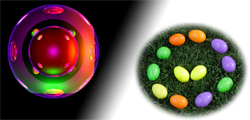
- A solid sphere with a translucent sphere in front over a checkerboard
- Yours need not match this, but you get the idea.
- Your best most creative effort.
- On this one, have fun and impress me.
At a minimum, the first image should illustrate that your system properly reflects the checkerboard on the underside of the sphere.
The second image should be arranged so that the solid sphere is viewed partially through the translucent sphere so that refraction is evident.
These first two scenes, and of course all they entail relative to what your system properly does, are worth 95 points for this assignment.
For the last scene, this is your chance to be creative and have fun with models you might pick up on the web. You can receive up to an additional 10 points for this last scene, and yes that does add up to 105 points (possible extra credit).
Required Features and Scenes:
This may seem like a lot to ask in four and a half weeks, and it is. But, if you pace yourself and take this assignment in steps, it is something you all should be able to accomplish. However, if you wait two and a half weeks and start, you may well find it to be overwhelming. So, here is some advice on how to break the project into manageable steps. It is by no means required that you proceed this way, but for anyone feeling unsure how to get started, here is one sound way of breaking the task into more manageable pieces.
Step 1: Write a program that reads a camera specification, a lighting specification for one light, and a model that is nothing more than a sphere that fills half the field of view.
Step 2: Implement that ray generation loop, one per pixel, map the rays to world coordinates, find the 3D point of intersection with the sphere (if any) for each ray and print the 3D coordinates - look, no image yet. However, at this point be thinking about ray generation as a generalized unctionality that can be invoked recursively; there are multiple psuedocode examples of appropriate logic on the web.
Step 3: For each point where a ray intersects the sphere, print the surface normal, direction back to the camera, the angle of reflection, and the angle to the light source(s). Also print for each ray the RGB values associated with diffuse and specular reflection at the given point of intersection on the object. Again, no image yet. Now step back and carefully examine what you are printing - does it seem correct?
Step 4: Make an image. You have essentially completed the first draft of the ray tracer, so now just write the RGB values into an image data structure and then write that image to a file. The Portable Bitmap image format is strongly recommended for shear simplicity.
Step 5: Add triangles and build the checkerboard out of paired triangles of the same size to make up squares.
Step 6: Add the recursive component to the ray tracer along with a specular reflection ray to allow one object to reflect in another, specifically the checkerboard in the sphere.
Step 7: Add a refraction ray capability, and use it with a the translucent sphere.
Formalities:
You are being permitted the latitude of implementing your ray tracer on essentially any computing platform, so long as you can demonstrate the system running on campus to the instructor and optionally to the class as a whole. Part of your demonstration to the instructor will include a code walk through, so the source code must be present and easily modified and re-run.
You are also required to submit a tar file to the instructor including all your source code and one image of each of the three scenes described above. This tar file will be submitted through RamCT.
Most students will choose to write their ray tracers in C, C++, Java, Python or some combination of the above. If you wish to use a language other than these you need prior approval of the instructor.
Ray Tracers, while moderately complicated, are relatively self contained in nature and you should not find yourself in need of using major external libraries. If you wish to use open source libraires beyond those commonly supplied with your language of choice, you should first obtain the permission of the instructor. So, for example, a standard vector package would likely be approved. In contrast, a package that performs ray intersection with common shapes would probably not be permitted, as it starts to overlap functionality you are expected to understand and implement yourself.