
Motivation
In the first assignment, you wrote code to read and manipulate a 3D model from a file in ply format. For this assignment, you will take the first step in rendering a model using a ray casting algorithm. More precisely, you write a program that reads in a camera model and one or more objects (one in this assignment), and produces a a pseudo-colored depth image in which color indicates relative distance from the image plane. This distance is a critical value computed and returned by the basic ray to polygon intersection code. While the resulting scene is not a realistic rendering, the code for manipulating camera geometry, casting rays, determining closeset points of intersection, etc. will all be readily extended in the following assignment to handle light sources and generate true renderings.
Task
Your program will take in three or more command line arguments. The first argument is a file containing the camera model. The last argument is the name of the image your program will write. In between are the names of ply model files. For this assignment you may assume a single object model file only, but consider generalization to many models now since it will become a requirement in the next assignment.
Your program will implement the camera model by throwing a ray from the focal point through each camera pixel, and determining whether that ray intersects any of the polygons in any of the models. If it does, the corresponding pixel should be set to a color value indicating the relative depth of that point. The precise algorithm for determining color will be supplied below so that all assigments generate consistent coloring. Should a ray fail to interesct any polygon then it is given a default background color; for this assignment set this default to (239, 239, 239). Your program will then write out the resulting image as an ASCII PPM color image (P3 format, see below for more detail) to the filename in the last argument passed to your executable.
Data Formats
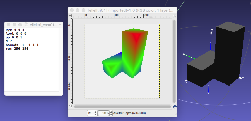
Here are the contents of a sample camera file:
				eye 4 4 4
 look 0 0 0
 up 0 0 1
 d 2
 bounds
				-1 -1 1 1
 res 256 256
The contents of the camera specification should be familiar to you now. The first three lines supply the location of the focal point, the look at point, and the up vector. Then comes the focal length, i.e. the distance from the focal point to the image plane. Pay particular attention to the last two arguments. The 'bounds' values indicate the minimum and maximum extend of the bounded image rectangle on the infinite image plane in the camera horizontal and vertical directions respectively. Then the resolution values seperately indicate the pixel sampling resolution across the horizontal and vertical dimensions of the bounded rectangle. One feature of this specification format is that you can generate intermediate cameras with low resolution, say 8 by 8 or even 4 by 4, when developing and debugging code. This speeds development considerabley. Do note that the dimensions of your output image must match the resolution specification exactly; no off by one errors allowed.
For this assignment you may assume that the row structure, including the single word headers on each line, do not change in a camera specifications file. For the moment you need not ignore comment lines, but that may come in future assignments.
Images should be written as legal ASCII PPM files. Although some variations are permissible, I recommend the following. The first line contains the characters P3 and nothing else. The next line contains the image width, the image height, and the number 255 (the maximum possible pixel value), all integers. Pixel values begin on the next line, and contain 3 values per pixel (a red value, a green value, and a blue value, in that order). Since the total number of pixels in an image is width times height, the number of values in the file (after the two header lines) must be 3 times width times height. To make images “readable” by humans (when they are small), I recommend putting a newline at the end of each row. The image generated for the camera model above might therefore begin with:
				P3
 256 256 255
 239 239 239 239 239 ...
The models to be used in this assignment are specified in ASCII PLY format. However, and this is a major simplification from your standpoint, for this assignment faces must be limited to 3 vertices. In other words, you need only consider the intersection of a ray with a triangle in this assignment.
Relative Depth
You encoding of relative depth must follow exactly the following
specification. First, when your algorithm completes ray casting for
every pixel, record the
tmin
and
tmax
values. To be clear, these are the minimum and maximum distances from
pixels to first polygons as determined by the t value returned when a
ray intersects a polygon. Then, for every pixel intersecting a
polygon, use the resulting
t
value to determine color as follows:
				ratio = 2 * (t - tmin) / (tmax - tmin)
 r = max(0, 255 * (1 -
				ratio))
 b = max(0, 255 * (ratio - 1))
 g = 255 - b - r
Credit where credit is due, this simple code for generating a thermal color map originated from a post by John1024.
Notice that to create the color coding your code most have determined all t values. A brute force approach is a two pass system that essentially ray casts the scene twice. Better, but not required, would be to use an intermediate data structure to store the necessary ray casting results for the entire image prior to creating the final color coded output image.
Examples
You are being provided two models and five camera files along with the output images generated by the reference system for this assignment. While your output may not match perfectly, it should come very close. All the example files, unix encoded, are included in the following zip file:
Here is a montage showing the first example camera, output image, and a view of the ellell model using the MeshLab software.
Submission
Make a tar file that includes all of the code, camera files, and model files necessary to demonstrate your program. For grading, you must name your executable 'raytracer' and it must for this assignment take exactly three arguments as described above.
Before submitting your tarball, please check Piazza post for safe grading.
Reminder
There is no “late period”. The program is due when it is due. All work you submit must be your own. You may not copy code from colleagues or the web or anywhere else. Cheating will not be tolerated, and will be handled in accordance with university and department policy.
Addendum (Last update 10/19/16)
In working through a question with a student posted on Piazza I created an example even simpler that what you currently have provided to you.
You may find this example helpful in debugging your code.
Here is a general tip. In a clean and simple implementation there should no need to ever create a 4x4 transformation matrix. Pay close attention the to way rays are generated on the image plane in the Sage worksheet for Ray Tracing camera geometry