Introduction to Computer Graphics
Fall 2020
CS 410 P3 - Adding Reflection, Polygons and Materials

Motivation
In the first assignment, you wrote code to read and manipulate 3D models in .obj format. In the second assignment, you wrote code to perform ray casting with ambient and diffuse lighting. In this assignment, you will combine those and implement three more features in your ray tracer:
- "mirror-like" reflection from models and spheres;
- objects occluding light sources from reaching other objects, i.e. shadows;
- specular highlights to further improve the realism of our lighting model.
Data Formats
The driver files used for this assignment are the same as in previous assignments with the following modifications:
- There will now be a line specifying the recursion depth, e.g.
recursionlevel
					3
. As in the SageMath notebooks, a recursion level of zero corresponds to no recursive ray tracing, like the second assignment. - We previously did not use the Ks and Kr values for spheres, but we will now. Ks is the amount that specular light should be attenuated. Kr is the amount that reflected rays should have their resulting color attenuated. The specular exponent for spheres will always be 16, as discussed in lecture.
- In addition to spheres, models may be listed to render. They will
have the same format as in the first assignment (
load
					model.obj
). Keep in mind any previous transformation commands are to be applied to the model during loading. - Each .obj file will have a line
mltlib file_name, wherefile_nameis a .mtl file as described on Wikipedia and in lecture. The .obj file will also have lines such asusemtl shinyredthat signify all faces after that line and before the next usemtl line should use the specified material in the .mtl file. For our purposes, we will currently only consider the Ka (ambient), Kd (diffuse), Ks (specular), Ns (specular exponent), and illum (illumination model) values. Ka, Kd, and Ks specify the reflectivity of the object for each kind of lighting, much as with spheres. Ns specifies the specular exponent, as discussed in lecture. The illum value is used for determining if a model is "mirror-like" in its reflection. The only illum values we will consider currently are 2 (no mirror-like reflection) and 3 (mirror-like reflection with Kr=Ks). More will be said about these material files in lecture.
Task
This assignment intentionally combines the previous two assignments and builds from them. It is recommended that as you complete this assignment, you simplify and improve your code where possible to make these and upcoming changes easier. It is also recommended that you implement the modifications in the following order:
- Implement specular reflections. For details of how this should be done, reference the SageMath notebooks presented in lecture.
- Implement shadows. This can be done by testing if each light source has a clear path to a point where a collision has ocurred, i.e. the point being illuminated. If not, that light does not contribute to the illumination of that surface point.
- Implement models and .mtl file parsing.
- Implement a recursive ray tracer. For details of how this should be done, reference the SageMath notebooks presented in lecture.
At a minimum you need to write code which takes the examples provided here in the form of driver files, .obj files, and .mtl files, and renders images comparable to those you are being provided. In grading you should expect us to test with additional files. Keep in mind will will not intentionally go out of our way to build ill-formatted input files. That said, you should make some modest effort to protect your code from trivial differences. A good example is one white-space equals many white-spaces whenever parsing a file. As to the substance of rendering, there should be no artificial limits on the number of spheres, polygonal objects, and light source.
Here are the links to download the driver file examples including models as well as sample output. As of November 3 there is now one file with four examples including drivers, models and sample output/resutls. ALSO - please download the corrected examples posted on 11/09/2020 at 6:00PM
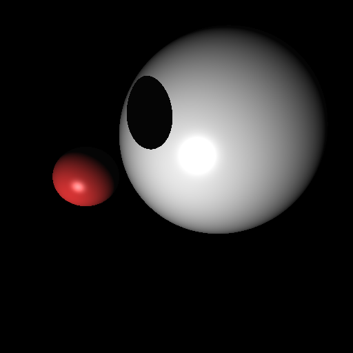
- Scene 0 - the scene described in driver00.txt. Expected output is below.
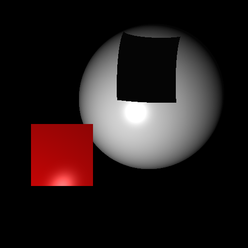
- Scene 1 - the scene described in driver01.txt. Expected output is below.
In all cases the camera view, lighting, and object placement should result in a well rendered final image. The image should be written in PPM format as described in P2.
Submission
Submit a zip or tar file via the CANVAS assignment page that includes:
- Your source files
- Your driver files
- Your model and material files
- Libraries if you use any
- A makefile if appropriate
- README.txt file that explicitly contains (1) A command to compile your program and (2) A command to execute it.
If you are using C++, your executable should be named 'raytracer'. If your are using java, the main executable class should be named 'Raytracer'. Notice the change in case for the first letter between C++ and Java. It is necessary for this assignment to take exactly two arguments as described above.
Reminder
The late policy for programming projects this semester is summarized in the course syllabus. All work you submit must be your own. You may not copy code from colleagues or the web or anywhere else. Cheating will not be tolerated, and will be handled in accordance with university and department policy.
Addendum (11/10/2020)
Please follow the instructions for switching triangle surface normals described at the start of lecture on 11/10/2020. To summarize the approach, if the dot product of a vector pointing back toward the camera (or where the ray began) and the surface normal is negative, flip the sign of the surface normal.